LED - 3. Let's make a large led display - Part 2 (Prepare Raspberry Pi with RGB Matrix Bonnet)
Many part of this document is derived from Adafruit RGB Matrix + Real Time Clock HAT for Raspberry Pi.
I will use the Bonnet type. If you are using the HAT type, go to https://learn.adafruit.com/adafruit-rgb-matrix-plus-real-time-clock-hat-for-raspberry-pi and solder the HAT first.
I used Adafruit RGB Matrix Bonnet which is suitable for Raspberry Pi Zero. However, the GPIO pinouts are the same, so you can use it on Raspberry Pi 3B, 3B+. To prevent shorts caused by contact between the bonnet and the Raspberry Pi, I filled vinyl between the Bonnet and Pi.
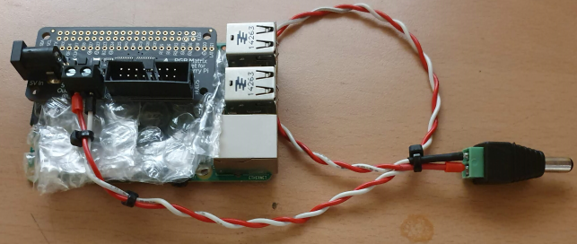
The RGB matrix Bonnet's barrel jack accepts 5V power and shares the Pi's 5V rail. So in theory, the Raspberry Pi can be operated from the bonnet power supply without the need for a separate 5V supply. But Adafruit recommands to use an independent 5V supply for Pi.
Shut down your Pi and remove power. Plug the HAT or Bonnet on so all the 2x20 pins go into the GPIO header.


You can power the Pi via the 5V wall plug that is also used for the Matrix but its best to have it powered seperately.
Later I'll connect 2 RGB Matrix, so I recommand 10A or higher power adapter.
We have a script that downloads the code and any prerequisite software. It works with the current Raspbian “Buster” (or earlier “Stretch”) operating system (either the Lite or Desktop version). I recommand the Lite version which doesn't have a GUI Desktop:
Tips: In the next post(LED - 5. Let's make a large led display - Part 6 (Playing movie and noise problem) ), I would recommend using Jessie(old version Rasbian) over Buster. See the post to check the reason.

Next the script will ask you what kind of adapter you’re using between the Pi and RGB matrix: either an Adafruit RGB Matrix Bonnet, or RGB Matrix HAT with RTC. If you select the latter, you’ll also be asked if you want to install additional drivers for the realtime clock.

I'm using the Bonnet, so I selected 1. But if you have HAT, select 2.
Then you’re asked whether you need the absolute best image possible from the LED matrix, or can accept slightly reduced quality for the sake of simplicity.
The script will confirm your selections and offer one more chance to cancel without changes.
There’s a lot of software to update, download and install, so it may take up to 15 minutes or so to complete. Afterward, you’ll be asked whether you want to reboot the system. If you’ve selected to install RTC support (for the Matrix HAT + RTC) or have made a change in the “quality” vs “convenience” setting, a reboot is required.
All other settings (LED matrix size, number of “chained” matrices and so forth) are specified at run-time.
All of the examples — and any code using the companion libraries — accept a common set of command-line switches for specifying the LED matrix size and other options. Among the more vital options are:
Specifies the number of rows (or height or the number of pixels vertically) of your LED matrix (or matrices, if you have several chained…they all need to be the same size though). Default value if unspecified is 32. Maximum value with the Adafruit RGB Matrix HAT + RTC is 32. Maximum with the RGB Matrix Bonnet is 64.
Specifies the number of columns (or width or the number of pixels horizontally) of your LED matrix/matrices. Default value if unspecified is 32.
Specifies the number of matrices in the chain…the output of one connects to the input of the next. Default value if unspecified is 1.
For Raspberry Pi 3 use a slowdown of 1 to start (use higher values if image still flickers). For Raspberry Pi 4, use a slowdown of 4. Older Pi models might work with 0, try it.
There are still many additional options but they’re increasingly esoteric and might only be needed with RGB matrices from other sources. For a complete explanation of these options (and a more in-depth explanation of the options above) see the documentation accompanying hzeller’s code repository.
Again, more documentation is available in the library author’s repository, and some of the examples show how to specify the matrix size and chain length in code rather than command-line selections every time.
While the
I will use the Bonnet type. If you are using the HAT type, go to https://learn.adafruit.com/adafruit-rgb-matrix-plus-real-time-clock-hat-for-raspberry-pi and solder the HAT first.
Raspberry with RGB Matrix Bonnet
Plug HAT/Bonnet into Raspberry Pi
I used Adafruit RGB Matrix Bonnet which is suitable for Raspberry Pi Zero. However, the GPIO pinouts are the same, so you can use it on Raspberry Pi 3B, 3B+. To prevent shorts caused by contact between the bonnet and the Raspberry Pi, I filled vinyl between the Bonnet and Pi.
The RGB matrix Bonnet's barrel jack accepts 5V power and shares the Pi's 5V rail. So in theory, the Raspberry Pi can be operated from the bonnet power supply without the need for a separate 5V supply. But Adafruit recommands to use an independent 5V supply for Pi.
Shut down your Pi and remove power. Plug the HAT or Bonnet on so all the 2x20 pins go into the GPIO header.
Connect Matrix Power cable to terminal block
Your RGB matrix came with a red & black power cable. One end has a 4-pin MOLEX connector that goes into the matrix. I modified the cable like this picture. Original cable's spade connector is not suitable for the Bonnet's 5V output terminal.
<My cable>

<original cable spade connector>
Connect RGB Matrix Data cable to IDC
The RGB matrix also came with a 2x8 data cable.
Connect one end to the matrix's INPUT side and the other end to the IDC
socket on the HAT/bonnet.
It wont damage the matrix if you accidentally get the cable connected to the output end of the matrix but it wont work so you might as well get it right first time!
In the figure below, connect the Hub75 interface to the bonnet where the arrow starts. Be careful to connect the VCC and GND of the 5V power supply correctly.
Power up your Pi via MicroUSB (optional but suggested)
Connect your Raspberry Pi to power via the microUSB cable, just like you normally would to power it up.You can power the Pi via the 5V wall plug that is also used for the Matrix but its best to have it powered seperately.
Plug in the 5V DC power for the Matrix
OK now you can plug in your 5V 4A or larger wall adapter into the HAT/bonnet. This will turn the green LED on but nothing will display on your matrix yet because no software is running!Later I'll connect 2 RGB Matrix, so I recommand 10A or higher power adapter.
Log into your Pi to install and run software
OK now you are ready to run the Pi software. You will need to get into a command line via the HDMI monitor, ssh or console cable. You will also need to make sure your Pi is on the Internet via a WiFi or Ethernet connection.We have a script that downloads the code and any prerequisite software. It works with the current Raspbian “Buster” (or earlier “Stretch”) operating system (either the Lite or Desktop version). I recommand the Lite version which doesn't have a GUI Desktop:
Tips: In the next post(LED - 5. Let's make a large led display - Part 6 (Playing movie and noise problem) ), I would recommend using Jessie(old version Rasbian) over Buster. See the post to check the reason.
curl https://raw.githubusercontent.com/adafruit/Raspberry-Pi-Installer-Scripts/master/rgb-matrix.sh >rgb-matrix.sh
sudo bash rgb-matrix.sh
When first run, the script will explain its plans and give you the option to cancel.
Of particular note here: any existing installation will be replaced. If there is a directory called “rpi-rgb-led-matrix” in the current working directory, its contents will be overwritten. Additionally, a Python module is installed and will replace anything currently there. If this is a problem, cancel and make a backup. Otherwise, sometimes reinstalling is exactly what you want.
Of particular note here: any existing installation will be replaced. If there is a directory called “rpi-rgb-led-matrix” in the current working directory, its contents will be overwritten. Additionally, a Python module is installed and will replace anything currently there. If this is a problem, cancel and make a backup. Otherwise, sometimes reinstalling is exactly what you want.
Next the script will ask you what kind of adapter you’re using between the Pi and RGB matrix: either an Adafruit RGB Matrix Bonnet, or RGB Matrix HAT with RTC. If you select the latter, you’ll also be asked if you want to install additional drivers for the realtime clock.
I'm using the Bonnet, so I selected 1. But if you have HAT, select 2.
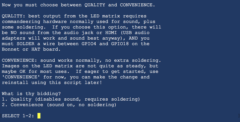
Then you’re asked whether you need the absolute best image possible from the LED matrix, or can accept slightly reduced quality for the sake of simplicity.

The “quality” option comes at a cost. First, you need to solder a jumper wire between GPIO4 and GPIO18
on the Bonnet or Hat board. Also, the normal sound output of the
Raspberry Pi must be disabled. You can still use a USB sound adapter if
needed, but audio over HDMI or from the 1/8" jack will not be present.
The “convenience” setting requires no changes and sound still works. For many casual projects this might look good enough. There’s an occasional bit of flicker from the matrix, that’s all.
If you’re not sure, or if you just want to get started experimenting with your new gadget, select “convenience” for now. You can make the change and reinstall the software later if needed.
If you’re not sure, or if you just want to get started experimenting with your new gadget, select “convenience” for now. You can make the change and reinstall the software later if needed.
The script will confirm your selections and offer one more chance to cancel without changes.
There’s a lot of software to update, download and install, so it may take up to 15 minutes or so to complete. Afterward, you’ll be asked whether you want to reboot the system. If you’ve selected to install RTC support (for the Matrix HAT + RTC) or have made a change in the “quality” vs “convenience” setting, a reboot is required.
All other settings (LED matrix size, number of “chained” matrices and so forth) are specified at run-time.
Testing the Examples
The installer creates a directory calledrpi-rgb-led-matrix, and inside this is a subdirectory examples-api-use with a few programs we can use to experiment with the matrix and confirm everything’s working.All of the examples — and any code using the companion libraries — accept a common set of command-line switches for specifying the LED matrix size and other options. Among the more vital options are:
--led-rows=(rows)Specifies the number of rows (or height or the number of pixels vertically) of your LED matrix (or matrices, if you have several chained…they all need to be the same size though). Default value if unspecified is 32. Maximum value with the Adafruit RGB Matrix HAT + RTC is 32. Maximum with the RGB Matrix Bonnet is 64.
--led-cols=(columns)Specifies the number of columns (or width or the number of pixels horizontally) of your LED matrix/matrices. Default value if unspecified is 32.
--led-chain=(chained)Specifies the number of matrices in the chain…the output of one connects to the input of the next. Default value if unspecified is 1.
Here’s how to run one of the examples — a rotating colored square.
Because this code is performing low-level hardware operations, it must
be run using the
That’s for a single 32x16 pixel RGB matrix. If you have a different size, change the
There are 12 different examples in the demo program (0 through 11), chosen with
Depending on your matrix type and Raspberry Pi model, some additional options may need fine-tuning:sudo command:sudo ./demo -D0 --led-rows=32 --led-cols=16That’s for a single 32x16 pixel RGB matrix. If you have a different size, change the
--led-rows and/or --led-cols values. Add a --led-chain value if multiple matrices are chained.There are 12 different examples in the demo program (0 through 11), chosen with
-D. For a full list of the program’s options, just type demo.--led-slowdown-gpio=(0…n) Sometimes needed to throttle back the speed when using a fast Pi. Default is 1.For Raspberry Pi 3 use a slowdown of 1 to start (use higher values if image still flickers). For Raspberry Pi 4, use a slowdown of 4. Older Pi models might work with 0, try it.
--led-rgb-sequence=(RGB order) Some LED matrices may
have their red, green and blue LEDs wired up in a different order…for
example, if you need to swap the green and blue channels, use --led-rgb-sequence=RBG. Default is RGB.--led-pwm-bits=(1…11) For long matrix chains you’ll
probably need to use fewer PWM bits, sacrificing some color fidelity to
improve refresh speed. Default is 11.There are still many additional options but they’re increasingly esoteric and might only be needed with RGB matrices from other sources. For a complete explanation of these options (and a more in-depth explanation of the options above) see the documentation accompanying hzeller’s code repository.
Using the Python Library
Some Python examples are included in therpi-rgb-led-matrix/bindings/python/samples directory. The matrix installer script has already loaded the prerequisite Python Imaging Library and installed the rgbmatrix module for both Python 2.7 and Python 3.Again, more documentation is available in the library author’s repository, and some of the examples show how to specify the matrix size and chain length in code rather than command-line selections every time.
While the
rgbmatrix module provides its own drawing
operations, it can also work with the Python Imaging Library as an
“offscreen canvas” that’s then issued to the matrix with the SetImage()
or SwapOnVSync() function — see the examples with “image-” in their
name.


댓글
댓글 쓰기