LED - 9. RGB LED Matrix Drive with ESP 32 without shield
"ESP32 is a series of low-cost, low-power system on a chip microcontrollers with integrated Wi-Fi and dual-mode Bluetooth. The ESP32 series employs a Tensilica Xtensa LX6 microprocessor in both dual-core and single-core variations and includes built-in antenna switches, RF balun, power amplifier, low-noise receive amplifier, filters, and power-management modules. ESP32 is created and developed by Espressif Systems, a Shanghai-based Chinese company, and is manufactured by TSMC using their 40 nm process.[2] It is a successor to the ESP8266 microcontroller."
ESP32 is a Dual Core MCU
The predecessor of ESP32, the ESP8266 has a builtin processor. However due to multitasking involved in updating the WiFi stack, most of the applications use a separate micro-controller for data processing, interfacing sensors and digital Input Output. With the ESP32 you may not want to use an additional micro-controller. ESP32 has Xtensa® Dual-Core 32-bit LX6 microprocessors, which runs up to 600 DMIPS. The ESP32 will run on breakout boards and modules from 160Mhz upto 240MHz . That is very good speed for anything that requires a microcontroller with connectivity options.The two cores are named Protocol CPU (PRO_CPU) and Application CPU (APP_CPU). That basically means the PRO_CPU processor handles the WiFi, Bluetooth and other internal peripherals like SPI, I2C, ADC etc. The APP_CPU is left out for the application code.
It is quite attractive that the esp32 has two cores and one dedicated to the communication protocol for stable system operation.
Installing ESP32 software to your Arduino IDE
This article assumes you have Arduino IDE installed on your computer and know how to use it.To use the display we are also going to need to install some ESP32 libraries.
Installing with Boards Manager
As of this writing, the latest version is 1.04. If a newer version is available, always use the latest version.- Install the current upstream Arduino IDE at the 1.8.7 level or later. The current version is on the Arduino website.
- Start Arduino and open the File -> Preferences window.
- Enter
https://github.com/espressif/arduino-esp32/releases/download/1.0.4/package_esp32_index.jsoninto the Additional Board Manager URLs field. You can add multiple URLs, separating them with commas. - Open Boards Manager from Tools > Board menu and install esp32 platform (and don't forget to select your ESP32 board from Tools > Board menu after installation).

Be careful : If the ESP32 board is not recognized by the device manager of your PC, refer to the ESP32 board datasheet to install the appropriate USB driver.
Materials
Here's what you need for this post:- ESP32 D1 Mini(https://www.aliexpress.com/item/4000650306925.html?spm=a2g0s.9042311.0.0.27424c4ddoF5ko) : 1EA
- P3 64X32 RGB LED Matrix(https://www.aliexpress.com/item/32739844613.html?spm=a2g0s.9042311.0.0.27424c4dhZkpoQ) : 1EA
- Dupont cables
- LED Power cable : 1EA
- 5V 20A Power supply : 1EA

<ESP32 D1 Mini>

<Dupont cables>
I've customized the dupont cables for HUB75 connector.
Testing ESP32 Mini
After installation, connect the ESP32 to your PC using a USB cable and select the port from the Arduino IDE menu Tool-> Port.- In File->Examples->01.Basics->Blink, select the "Blink" example. And modify the source code like this. Because LED_BUILTIN was not defined when using ESP32.
int LED_BUILTIN = 2;
// the setup function runs once when you press reset or power the board
void setup() {
  // initialize digital pin LED_BUILTIN as an output.
  pinMode(LED_BUILTIN, OUTPUT);
}

// the loop function runs over and over again forever
void loop() {
  digitalWrite(LED_BUILTIN, HIGH);   // turn the LED on (HIGH is the voltage level)
  delay(1000);                       // wait for a second
  digitalWrite(LED_BUILTIN, LOW);    // turn the LED off by making the voltage LOW
  delay(1000);                       // wait for a second
}
// the loop function runs over and over again forever
void loop() {
  digitalWrite(pin, HIGH);   // turn the LED on (HIGH is the voltage level)
  delay(1000);                       // wait for a second
  digitalWrite(pin, LOW);    // turn the LED off by making the voltage LOW
  delay(1000);                       // wait for a second
}
- Click the upload icon, then the source code is compiled and transfer the ececutable to the ESP32.
- After the trasfering is completed, the ESP32's LED might blink
Installing PxMatrix and Adafruit GFX library to your Arduino IDE
I explained in detail at https://iot-for-maker.blogspot.com/2020/02/led-8-rgb-led-matrix-drive-with-esp.html. See this blog.Wiring
The GPIO pin configuration of ESP32 Mini is as follows. Refer to it when connecting with the LED matrix.
The GPIO34, 35, 36, 39 are for analog input only and should not be used for output. And GPIO 9 and 10 are also designated for serial communication.

<image from https://github.com/witnessmenow/WiFi-Tetris-Clock>
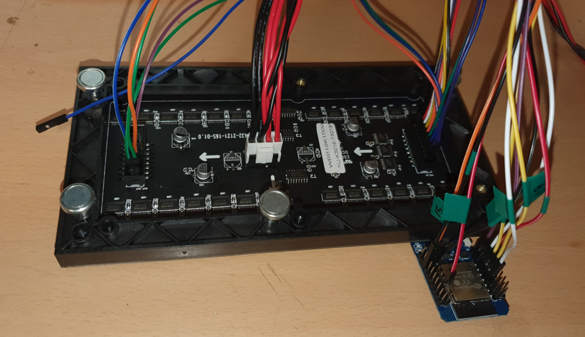
I connected the ESP32 to the 64x32 LED matrix with reference to the picture above like this.
Testing ESP32, 64X32 RGB LED matrix
After connecting, connect 5V power to LED Matrix, compile the following code in ESP32 and operate it. The test code is a mario example from https://github.com/2dom/PxMatrix/tree/master/examples. However, we need to modify this code a bit. The example code is a mix of 64X64 and 64X32 size test code.First, modify the initialization part of the display object as follows. E-pin is not used in 64X32 size.
// PxMATRIX display(matrix_width,matrix_height,P_LAT, P_OE,P_A,P_B,P_C);
PxMATRIX display(64,32,P_LAT, P_OE,P_A,P_B,P_C,P_D);
//PxMATRIX display(matrix_width,matrix_height,P_LAT, P_OE,P_A,P_B,P_C,P_D,P_E);
Add display.setMuxDelay (1,1,1,1,1) in setup function. In addition, the 64 × 32 size LED matrix uses a 1/16 scan rate, so the scan rate is modified to 1/16. I don't use a FM6126 A chip, so I disabled setDriverChips function.
  display.setMuxDelay(1,1,1,1,1);
  display.begin(16);
  //display.setDriverChip(FM6126A);
Finally, the loop function was modified to simply show the mario image.
void loop() {
  cnt++;
  delay(1000);
//  display.clearDisplay();

  drawImage2(0, 0);
  return;
}
After building the code and uploading it to ESP32, if you see the following picture, it works fine.

Make Tetris Clock
Once you've verified that the ESP32 and the 64X32 RGB LED matrix are in good working order, you can test Brian Lough's Tetris Clock.Tetris clock is detailed in https://github.com/witnessmenow/WiFi-Tetris-Clock. This example does not work on ESP8266, only on ESP32.

<Wifi Tetris Clock by Brian Lough>
First, modify the ssid and password values for WiFi access in the source code according to your environment. This program gets the current time through internet access, so WiFi access is essential.
// Initialize Wifi connection to the router
char ssid[] = "SSID";     // your network SSID (name)
char password[] = "password"; // your network key
Then modify the OE pin number. I'm using the general ESP32(D1 mini), so I'll use pin number 2.
// https://en.wikipedia.org/wiki/List_of_tz_database_time_zones
#define MYTIMEZONE "Europe/Dublin"
Then modify the display object initialization part to match the LED matrix you are using.
// PxMATRIX display(32,16,P_LAT, P_OE,P_A,P_B,P_C);
// PxMATRIX display(64,32,P_LAT, P_OE,P_A,P_B,P_C,P_D);
//PxMATRIX display(64, 32, P_LAT, P_OE, P_A, P_B, P_C, P_D, P_E);
PxMATRIX display(64, 32, P_LAT, P_OE, P_A, P_B, P_C, P_D);
Finally, modify the setup function as in the previous Mario example as follows.
  // Intialise display library
  display.setMuxDelay(1,1,1,1,1);
//  display.begin(16, SPI_BUS_CLK, 27, SPI_BUS_MISO, SPI_BUS_SS); // TinyPICO
  display.begin(16); // Generic ESP32 including Huzzah
  display.flushDisplay();
If you compile and upload the code, you will probably see the following output.

Wrapping up
It is very interesting to display the Tetris clock on the RGB LED matrix. The blog using ESP8266 is located at https://iot-for-maker.blogspot.com/2020/02/led-8-rgb-led-matrix-drive-with-esp.html. However, the Tetris clock does not work on the ESP8266.And one thing to keep in mind is the logic voltage. Arduino uses 5V logic voltage, so there is no problem, but boards like ESP8266, ESP32, Teensy use 3.3V logic voltage. Fortunately the above example worked, but there is no guarantee that the RGB LED matrix using 5V logic voltage will operate at 3.3V logic voltage. Due to this structural weakness, new RGB panels may not work at any moment.
You can download the source codes at https://github.com/raspberry-pi-maker/IoT/tree/master/led9-esp32 .


댓글
댓글 쓰기